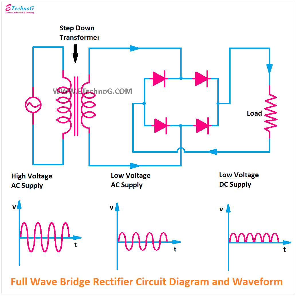
Bridge Rectifier Circuit Diagram And Waveform
Full wave bridge rectifier Circuit analysis Rectifier bridge circuit application applications basics diagram output waveform circuits diodes used functions diode voltage dc power resultant transformer advantages
bridge rectifier with regulator ic circuit Archives - theoryCIRCUIT
Full wave bridge rectifier circuit Rectifier wave circuit filter without bridge diagram tapped capacitor diodes center four type circuits board using circuitdigest electronic choose two Full wave bridge rectifier with diagram
Full wave rectifier circuit diagram (center tapped & bridge rectifier)
Rectifier circuit bridge diagram wave working detailsFull wave bridge rectifier circuit Bridge rectifier circuit regulator diagram ic wave tag theorycircuitFull wave bridge rectifier circuit.
Bridge rectifier with regulator ic circuit archivesRectifier bridge circuits Rectifier capacitor waveform prototypes theorycircuitExplain full wave bridge rectifier with diagram.

Different rectifier circuits and their working
Bridge rectifier: functions, circuits and applicationsRectifier bridge circuit wave diagram regulator ic Rectifier bridge wave circuit diagram diode voltage operation peak fig shown its below inverse value when negativeRectifier circuit wave.
Rectifier piv inverse peak engineeringtutorialFull wave bridge rectifier – circuit diagram and working principle Rectifier circuit diagramRectifier waveform.

Rectifier circuit diagram wave waveform output input
Rectifier principle .
.


bridge rectifier with regulator ic circuit Archives - theoryCIRCUIT

Full Wave Bridge Rectifier Circuit

Different Rectifier Circuits and their Working - Electroinvention

Full Wave Bridge Rectifier With Diagram - PCB Designs

Full Wave Bridge Rectifier – Circuit Diagram and Working Principle

Bridge Rectifier: Functions, Circuits and Applications - Utmel

Full Wave Bridge Rectifier Circuit

Full Wave Rectifier Circuit Diagram (Center Tapped & Bridge Rectifier)

Rectifier Circuit Diagram | Half Wave, Full Wave, Bridge - ETechnoG